Report abuse
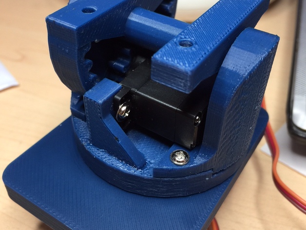


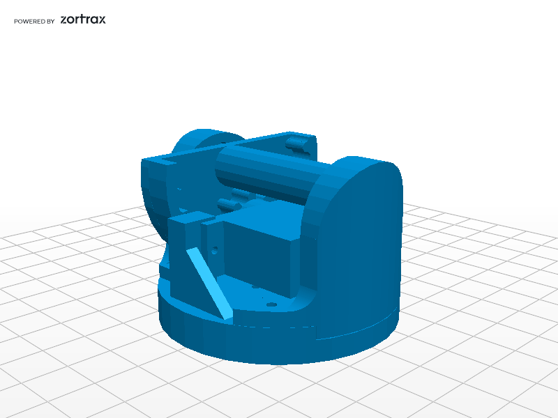
This pan tilt was made to be the base for my robot head (coming soon)
I needed a stable base with little play & a strong tilt.
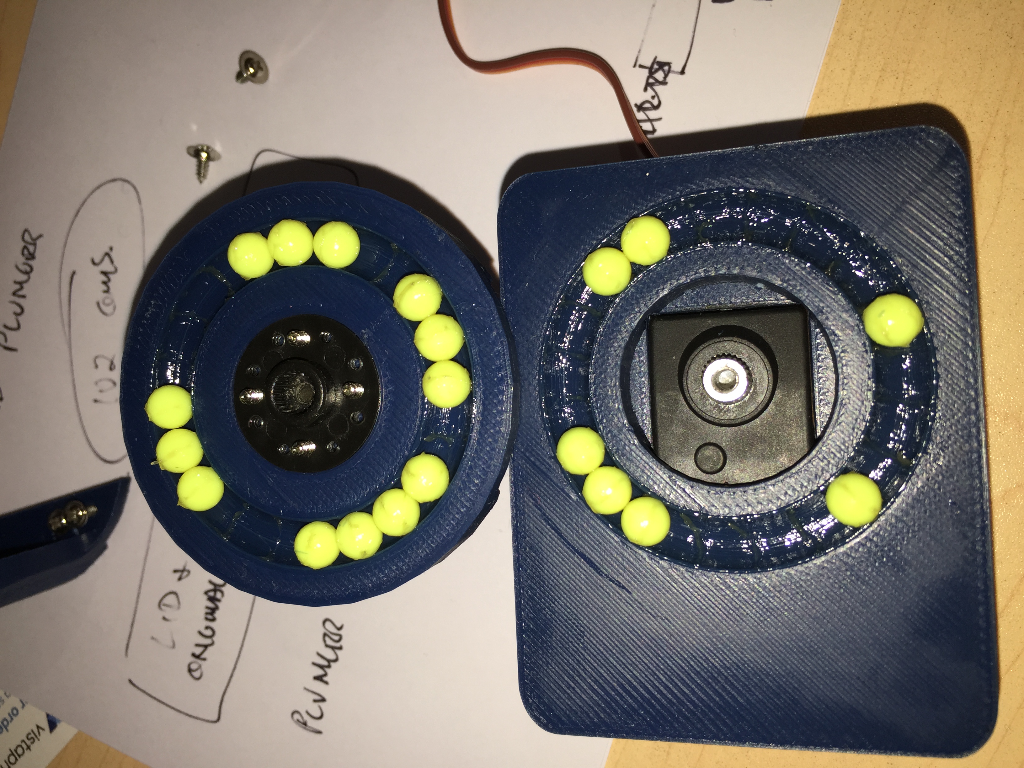
I used 6mm airsoft balls for the bearings, but any 6mm ball will do.
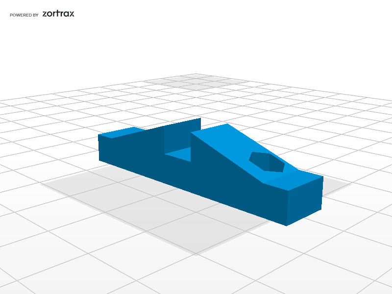
All the parts for the tilt mechanism are printed in one file.
The servo base is printed by itself.
I have printed the parts in the orientation that is in the file.
I used an Up2 printer on fine with 0.15mm layer height.
Bearings for the tilt pivot are : MR106 (10 x 6 x 3mm)
Servo for tilt is this one:
http://hobbyking.com/hobbyking/store/__45606__Corona_939MG_Digital_Metal_Gear_Servo_2_7kg_12_5g_0_13sec_AUS_Warehouse_.html
Servo for pan is this one:
http://hobbyking.com/hobbyking/store/__24578__Turnigy_TGY_4409MD_Metal_Gear_Digital_Servo_9_45kg_0_11sec_44g.html
To assemble the top plate/tilt mechanism:
Glue servo mounts to top pan plate. They are a tight fit so acetone can be used as the adhesive.
Glue the mounting plate to the gear/shaft assembly, being careful to place the holes in the mount where you want them & ensuring that the mount is aligned with the flat section of the gear on the opposite end of the shaft.
I placed the shaft on a flat surface with the flat of the gear against the bench & used this to align the other plate while gluing.
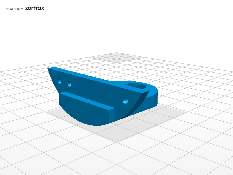
Press the bearings into the upright supports.
Place the gear/shaft assembly between the upright supports.
Glue the upright support without screw holes into the top pan plate, using the shaft as an alignment spacer. Screw the other upright into place using screws no longer than 8mm. This upright is made to be removable for disassembly. Don’t glue it in!!!! Screws longer than 8mm will damage the bearing surface on the other side.
I held all this together with rubber bands until the glue was well dried.
While glue is drying, paint a small amount of acetone into the pinion & allow the ABS to soften. Place the pinion onto the tilt servo drive & push it home. The acetone softens the plastic and it takes the shape of the splines in the servo drive. Screw the pinion down till its fully home & check pinion is square with the servo.
Once glue is well dried, remove the screwed on upright from the top plate & mount the servo. Ensure servo is centred & also that the tilt plate is in the position you want it when the pinion gear meshes.
Screw servo into place, making sure pinion has meshed fully with the shaft gear. Use screws no longer than 8mm. The servo I used had 2 small lugs on each mounting tab that I had to remove to ensure a flat mounting surface.
Once servo is mounted, replace upright & screw into place.
Once assembled, the shaft/gear can be removed by:
Removing the screwed in upright.
Removing the servo/pinion assembly
Rotating the gear 180 degrees. It will catch slightly at the bottom, but will turn.
The shaft can then be slipped out of the bearing in the glued upright.
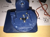
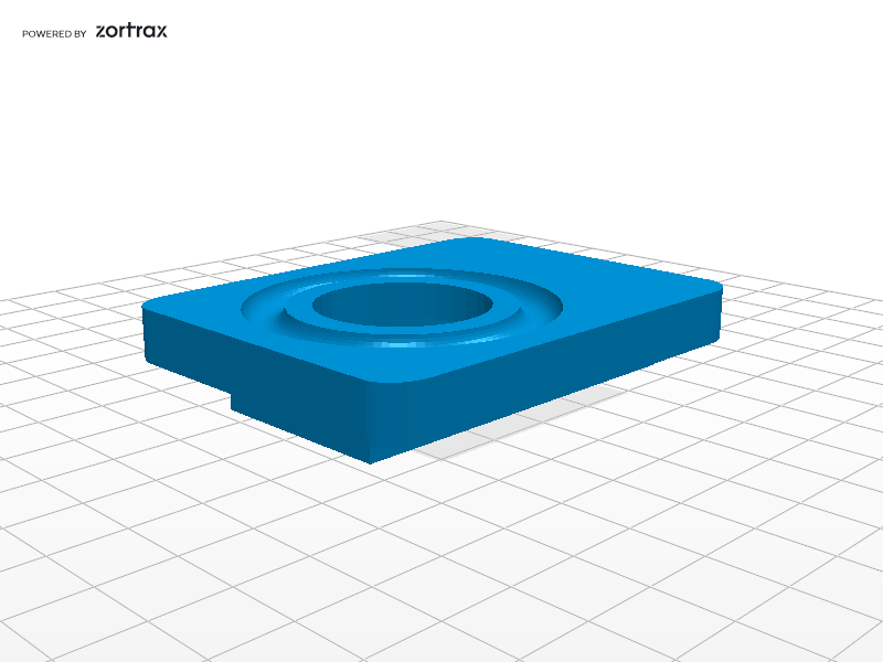
The lower servo mount is fairly straight forward.
The tilt plate will need to be disassembled to access the four screws that hold the upper plate on.
Screw the circular servo drive onto the upper plate using four screws. The recess in the upper plate will hold the drive concentric.
Screw the servo into place in the lower plate.
Once servo is mounted, insert the bearings (I forgot to count how many there are….) into the lower plate.
Place the top plate over the lower one, lining up the lower servo drive as you do.
Use the servo drive fixing screw to pull the top plate down onto the servo drive spline & bearings.
Be careful not to over tighten the screw or there will be too much load on the servo.
Just tight enough to remove all slop is all that is required. You may need a small amount of threadlocker to prevent screw from coming loose.
I hope these instructions are adequate.
If anyone prints one of these, I’d love to see it!
Video at: https://www.youtube.com/watch?v=1ZG92MYnioA
I’d also like to thank the following contributors:
http://www.thingiverse.com/thing:73555 – for giving me the idea to use airsoft bearings.
http://www.thingiverse.com/thing:507974 – for his excellent cylindrical gear SCAD code, without which, this project would not have been as easy.
Thank you gents!
| Last Update | Type | Downloads | Size | |||
|---|---|---|---|---|---|---|
|
|
Glued-upright.stl | 12 October 2015 |
.stl | 175 | 51,25 KB | |
|
|
Pinion.stl | 12 October 2015 |
.stl | 175 | 35,73 KB | |
|
|
Screwed-upright.stl | 12 October 2015 |
.stl | 175 | 59,36 KB | |
|
|
Servo-mounts.stl | 12 October 2015 |
.stl | 175 | 8,48 KB | |
|
|
Shaft-flat.stl | 12 October 2015 |
.stl | 176 | 10,63 KB | |
|
|
Shaft.stl | 12 October 2015 |
.stl | 175 | 112,68 KB | |
|
|
Tilt-base.stl | 12 October 2015 |
.stl | 179 | 531,63 KB | |
|
|
new_fred_head-Base.stl | 12 October 2015 |
.stl | 175 | 254,09 KB | |
|
|
tilt_mechanism_assembled.stl | 12 October 2015 |
.stl | 178 | 537,19 KB | |


Be the First to Comment!
You must be logged in to post a comment.
You must be logged in to post a comment.
Ball raced & geared pan tilt
by LekkybitsAdd this project to collection